Why Does The Transformer Need Capacitance Compensation?
Because all motors are inductive loads, power exchange will be carried out between the load and the power supply to form reactive power, which will reduce the power utilization rate of the power supply. If a compensation capacitor is added, the capacitor can provide capacitive reactive power. The inductive reactive power and capacitive reactive power are in the opposite direction, so the power exchange will be carried out between the inductive load and the capacitor. The power supply no longer needs to bear the reactive power exchanged, The utilization rate of power energy is greatly increased!
The power capacitor compensates the inductive load in parallel in the power network. The current vector of inductive load lags behind the voltage, which flows on the power supply transformer and line, reducing the active power, increasing the voltage loss of overhead line, and increasing the variable loss of transformer and overhead line.
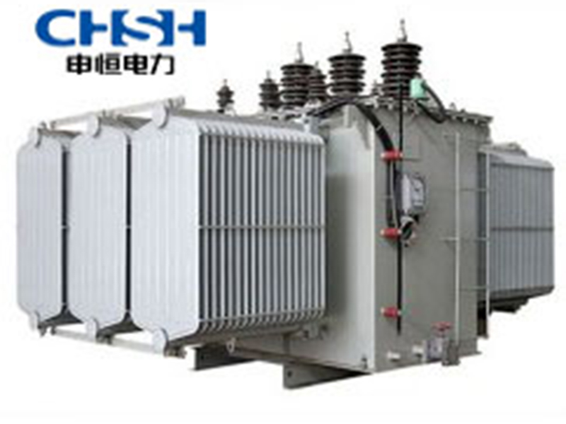
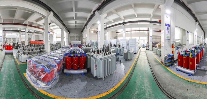
The shunt capacitor flows the leading current, which is 90 º ahead of the voltage, and is exactly opposite to the inductive current. Therefore, the inductive current in the power supply transformer is greatly reduced on the line, so that all the apparent power (capacity) of the transformer can be given to the active power. The line also flows almost all the active current. This is the principle of capacitance compensation. Cos if full compensation Φ= 1。 We don’t want full compensation, Cos Φ= 1 is parallel resonance, which may be dangerous. High voltage will be generated when the circuit quality factor Q is high. So Cos Φ Do not exceed 0.95 degrees. (End)
My understanding is to improve the quality factor, reduce the loss of useless work (internal resistance of transformer, line impedance, internal resistance of equipment), and improve the safety of transformer and line during high load operation.
It compensates phase angle, i.e. power factor, to reduce line loss caused by reactive current and remote voltage loss
What exactly does power capacitance compensate?
Answer: The structure of power capacitor is almost the same as that of ordinary capacitor. A capacitor is a container for storing electric charge. The utility model is composed of two metal sheets which are close together and are separated by insulating materials. The capacitor works by its charging and discharging function. When the power switch is not closed in the circuit, the two metal plates of the capacitor are not charged; When the switch is closed, free electrons on the positive plate of the capacitor are attracted by the power supply and pushed to the negative plate.
As far as shunt capacitors and power transformers are concerned, the inductive loads of shunt capacitors and power transformers resonate with each other and exchange electric energy. They are mainly used to compensate the reactive power of the inductive loads of the power system to improve the power factor, improve the voltage quality, reduce line losses, and improve the voltage quality and equipment utilization. Because a capacitor is a device that stores energy, it does not consume electricity. Its voltage in the AC circuit is 90 degrees ahead of the current.
When the average power P transmitted by the power supply is constant, according to I=P/Ucos Φ It can be seen that the current is inversely proportional to the power factor. If the power factor is low, the line current will increase. Since the transmission line itself has a certain impedance, on the one hand, it will increase the voltage loss on the line and reduce the voltage at the user end; On the other hand, it also increases the power loss △ P on the line.
Because △ P is proportional to the square of the current, that is, △ P=RI ²= R(P/Ucos Φ)², It can be seen that △ P is inversely proportional to the square of the power factor, and the low power factor will increase the power loss of the line every day. (where R is the line resistance).
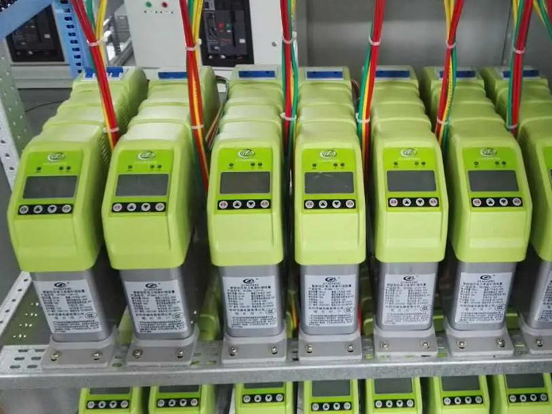
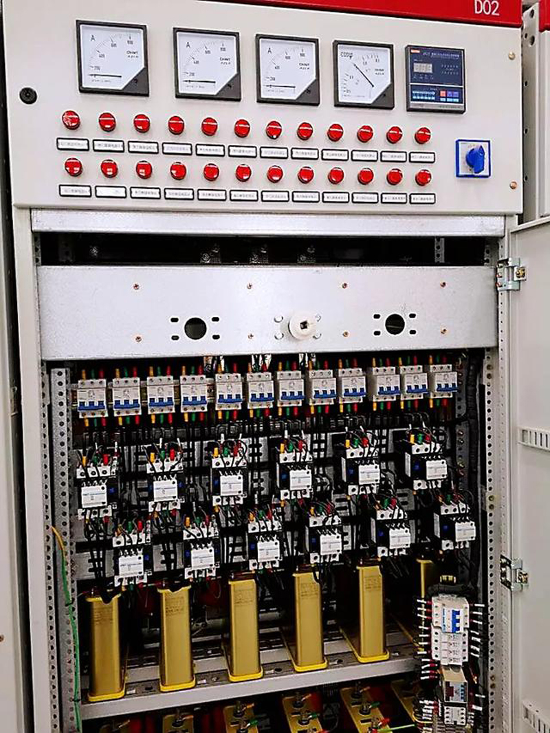
It can be seen that after the power factor is increased, on the one hand, the capacity of the power supply equipment can be fully utilized, and on the other hand, the loss of electric energy in the transmission process can be reduced. Therefore, improving the power factor of the power grid is of great practical significance to the development of the national economy.
The reason of low cost of power factor is that inductive load needs reactive power to establish magnetic field. There is energy exchange between reactive power and power supply. This energy exchange is necessary for the operation of inductive load and cannot be changed. In order to improve the power factor of the line, capacitors can be connected in parallel at both ends of the inductive load, and energy exchange can be conducted between capacitors and electrical and inductive loads to improve the power factor of the line and reduce the reactive power burden of the power supply.
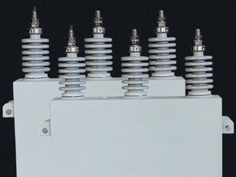
Capacitance is a physical quantity that measures the storage capacity of a conductor. When a certain voltage is applied to two mutually insulated conductors, a certain amount of electricity will be stored. One conductor stores a positive charge, and the other stores a negative charge, which has the same capacity as the positive charge. The higher the voltage applied to the two conductors, the more power is stored. The stored power is proportional to the applied voltage, and the ratio is called capacitance. If the voltage is expressed in U, the electric quantity is expressed in Q, and the capacitance is expressed in C, then there is a calculation formula of C=Q/U. The basic unit of capacitance is farad (F), which is also commonly used as micro method( μ f) , Na (nf) or Pi (pf). The relationship between them is 1F=10 ⁶ μ f、1 μ f=10 ³ nf、1nf=10 ³ pf。
⚡ There are many kinds of power capacitors, such as
① High voltage shunt capacitor with voltage of 1.05~35KV and capacity of 30~334kvar and 1000~5000kvar;
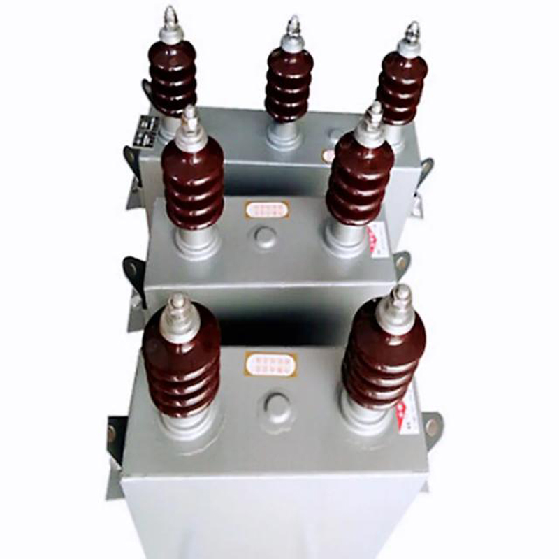
② Low voltage shunt capacitor, with voltage of 0.23~1.00kv and capacity of 5~50kvar;
③ Self healing low-voltage shunt capacitor, with voltage of 0.23~1.00kv and capacity of 1~150kvar;
④ Assembling shunt capacitor, its voltage is 3.15~38.5kv, its capacity is 1667~10000kvar for single phase and 1000~20000kvar for three-phase.
These parallel capacitors, which generally have strict requirements, are used for parallel connection in 50Hz or 60Hz AC power systems to compensate inductive reactive power, improve power factor, improve voltage quality, reduce line loss, and improve the active output of the system or transformer.
⚡ In addition, the functions of power capacitors include series capacitors, high-voltage AC filter capacitors, pulse capacitors, compressed gas capacitors, protective capacitors, DC filter capacitors, AC motor capacitors, coupling capacitors and capacitor voltage dividers, electric heating capacitors, circuit breaker capacitors, etc. Different capacitors have their own specific functions, which are omitted here.
♥ The structure of the capacitor is separated by insulating materials between the two electrode plates, so free electrons moved from the positive plate are stacked on the negative plate. When the number of electrons on the positive plate decreases, positive electricity is brought on, and the negative plate is brought on because of the increase of the number of electrons, so there is a potential difference between the two plates. When the potential difference is equal to the power supply voltage, the capacitor charging is ended. At this time, even if the power supply is disconnected, the capacitor can still keep the charging voltage unchanged.