- Home
- News
- The Essential Players in Electrical Systems: Decoding 10 Key Components’ Symbols and Functions
The Essential Players in Electrical Systems: Decoding 10 Key Components’ Symbols and Functions
In the complex landscape of electrical engineering, understanding component symbols is crucial for interpreting schematics and ensuring system safety. Here’s a breakdown of 10 fundamental devices, from their graphical representations to their vital roles in power distribution and control.
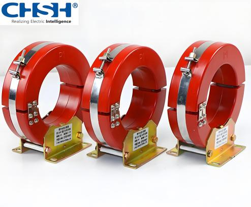
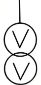
1. Double-Core Double-Winding Current Transformer
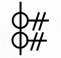
Symbol: Two interlinked coils with a vertical bar between them, denoting two iron cores (IEC 06-04-08).
Function: Converts high primary currents to lower secondary currents for measurement or protection. The dual cores allow independent current sensing for redundancy in relays or meters.
2. Circuit Breaker
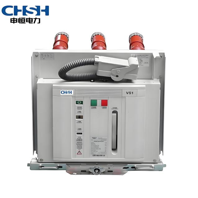
Symbol: A switch-like figure with arcs or dots beside the contacts (IEC 06-06-01).
Function: Automatically interrupts current during overloads or short circuits. Unlike fuses, it can be reset, making it reusable in distribution panels and substations.
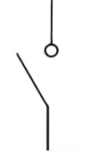
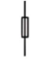
3. Isolator (Disconnect Switch)
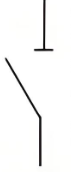
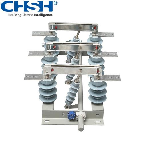
Symbol: A simple broken line with a horizontal bar, indicating a manual switch (IEC 06-02-01 variant).
Function: Physically separates an electrical circuit for maintenance, ensuring no current flows when open. It cannot interrupt load current and must be operated after circuit breakers.
4. Load Break Switch
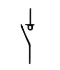
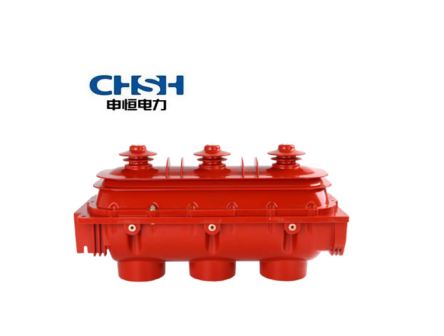
Symbol: Similar to an isolator but with additional contact arcs (IEC 06-02-06).
Function: Switches normal load currents but cannot handle fault currents. Used in distribution networks to isolate sections without full breaker complexity.
5. Contactor
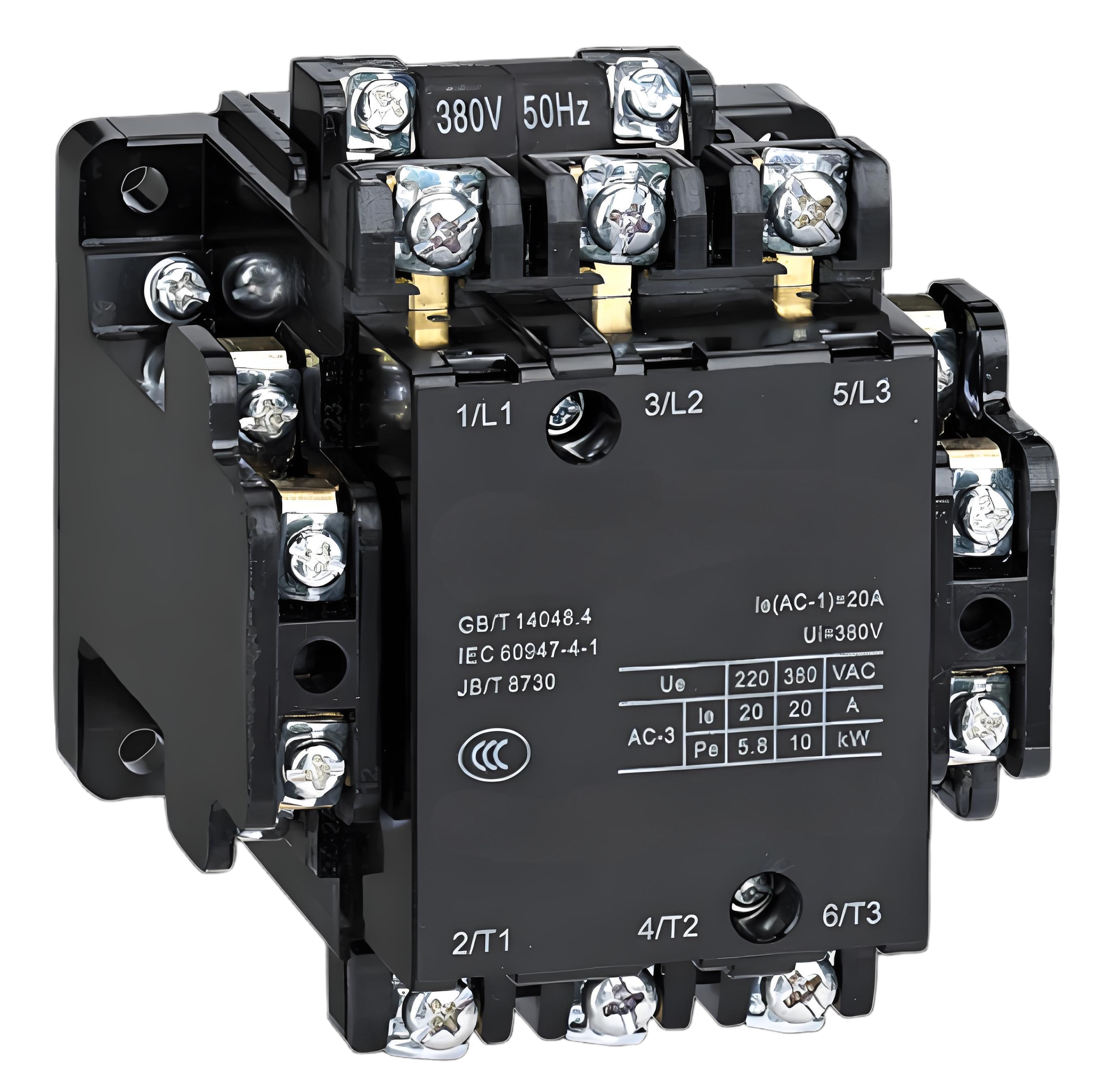
Symbol: An electromagnet coil with parallel lines representing contacts (IEC 06-02-12).
Function: Controls electric motors or large loads via an electromagnet. Activated by a low-power signal, it switches high-current circuits, essential in industrial automation.
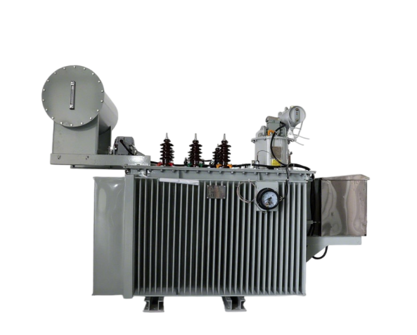
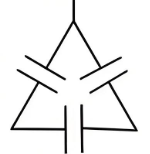
6. Three-Winding Transformer
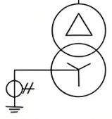
Symbol: Three interlinked coils, often with a Y or Δ configuration notation (IEC 06-04-02).
Function: Transfers power between three electrical circuits, enabling voltage transformation across multiple grids. Common in substations for voltage matching between transmission and distribution.
7. Voltage Transformer (Potential Transformer)
Symbol: A single coil pair with a zigzag or parallel lines (IEC 06-04-05).
Function: Steps down high voltages for measurement by meters or relays. Ensures safe voltage levels for instrumentation in power systems.
8. Fuse

Symbol: A zigzag line or a rectangle with a vertical bar (IEC 06-06-02).
Function: Sacrificial device that melts when overcurrent flows, breaking the circuit. Cheaper than circuit breakers but requires replacement after activation.
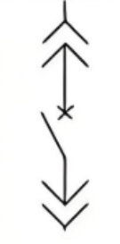
9. Lightning Arrester (Surge Protector)
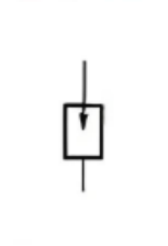
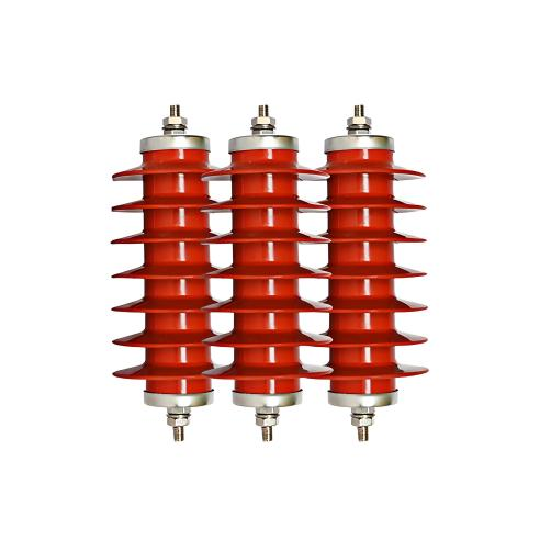
Symbol: A pointed triangle or zigzag line with an arrow (IEC 06-09-08).
Function: Protects equipment from voltage spikes (e.g., lightning). Conducts excess voltage to ground, preventing damage to sensitive electronics.
10. Capacitor
Symbol: Two parallel lines (fixed capacitor) or a variable zigzag line (IEC 06-13-01).
Function: Stores electrical energy in an electric field. Used for power factor correction, filtering, or energy storage in circuits.
The Language of Symbols: A Safety Imperative
These symbols, standardized by bodies like the IEC, form a universal code. For example, the circuit breaker’s arc symbol instantly signals its fault-interrupting capability, while the capacitor’s parallel lines denote its energy-storing nature. Misinterpretation risks catastrophic failures—hence why engineers worldwide rely on this visual grammar.
As smart grids evolve, symbols may adapt to digital interfaces, but their core purpose remains: translating complex systems into understandable blueprints. For anyone delving into electrical design, mastering these symbols is the first step toward safe, efficient engineering.
For more information about CHSH’s transformer products and their applications, please contact [Email: 457100923@qq.com] or visit [pr@shenhengpower.com].
Powering Tomorrow, Safely and Efficiently.
Issue Date: [I2025/6/27] | Media Inquiries: pr@shenhengpower.com | Tel/What’s app: +86-15039721372
CHSH – Realizing Electric Intelligence, Empowering Sustainable Power Networks.